Achieving the correct networking setup is crucial to a successful CloudStack installation. This section contains information to help you make decisions and follow the right procedures to get your network set up correctly.
Basic and Advanced Networking
CloudStack provides two styles of networking:.
Basic For AWS-style networking. Provides a single network where guest isolation can be provided through layer-3 means such as security groups (IP address source filtering).
Advanced For more sophisticated network topologies. This network model provides the most flexibility in defining guest networks, but requires more configuration steps than basic networking.
Each zone has either basic or advanced networking. Once the choice of networking model for a zone has been made and configured in CloudStack, it can not be changed. A zone is either basic or advanced for its entire lifetime.
The following table compares the networking features in the two networking models.
| Networking Feature | Basic Network | Advanced Network |
|---|---|---|
| Number of networks | Single network | Multiple networks |
| Firewall type | Physical | Physical and Virtual |
| Load balancer | Physical | Physical and Virtual |
| Isolation type | Layer 3 | Layer 2 and Layer 3 |
| VPN support | No | Yes |
| Port forwarding | Physical | Physical and Virtual |
| 1:1 NAT | Physical | Physical and Virtual |
| Source NAT | No | Physical and Virtual |
| Userdata | Yes | Yes |
| Network usage monitoring | sFlow / netFlow at physical router | Hypervisor and Virtual Router |
| DNS and DHCP | Yes | Yes |
The two types of networking may be in use in the same cloud. However, a given zone must use either Basic Networking or Advanced Networking.
Different types of network traffic can be segmented on the same physical network. Guest traffic can also be segmented by account. To isolate traffic, you can use separate VLANs. If you are using separate VLANs on a single physical network, make sure the VLAN tags are in separate numerical ranges.
VLAN Allocation Example
VLANs are required for public and guest traffic. The following is an example of a VLAN allocation scheme:
| VLAN IDs | Traffic type | Scope |
|---|---|---|
| less than 500 | Management traffic. Reserved for administrative purposes. | CloudStack software can access this, hypervisors, system VMs. |
| 500-599 | VLAN carrying public traffic. | CloudStack accounts. |
| 600-799 | VLANs carrying guest traffic. | CloudStack accounts. Account-specific VLAN is chosen from this pool. |
| 800-899 | VLANs carrying guest traffic. | CloudStack accounts. Account-specific VLAN chosen by CloudStack admin to assign to that account. |
| 900-999 | VLAN carrying guest traffic | CloudStack accounts. Can be scoped by project, domain, or all accounts. |
| greater than 1000 | Reserved for future use |
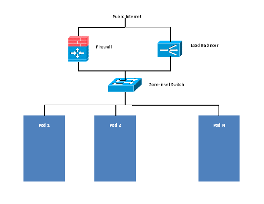
Example Hardware Configuration
This section contains an example configuration of specific switch models for zone-level layer-3 switching. It assumes VLAN management protocols, such as VTP or GVRP, have been disabled. The example scripts must be changed appropriately if you choose to use VTP or GVRP.
Dell 62xx
The following steps show how a Dell 62xx is configured for zone-level layer-3 switching. These steps assume VLAN 201 is used to route untagged private IPs for pod 1, and pod 1’s layer-2 switch is connected to Ethernet port 1/g1.
The Dell 62xx Series switch supports up to 1024 VLANs.
Configure all the VLANs in the database.
vlan database
vlan 200-999
exit
Configure Ethernet port 1/g1.
interface ethernet 1/g1
switchport mode general
switchport general pvid 201
switchport general allowed vlan add 201 untagged
switchport general allowed vlan add 300-999 tagged
exit
The statements configure Ethernet port 1/g1 as follows:
- VLAN 201 is the native untagged VLAN for port 1/g1.
- All VLANs (300-999) are passed to all the pod-level layer-2 switches.
Cisco 3750
The following steps show how a Cisco 3750 is configured for zone-level layer-3 switching. These steps assume VLAN 201 is used to route untagged private IPs for pod 1, and pod 1’s layer-2 switch is connected to GigabitEthernet1/0/1.
Setting VTP mode to transparent allows us to utilize VLAN IDs above 1000. Since we only use VLANs up to 999, vtp transparent mode is not strictly required.
vtp mode transparent
vlan 200-999
exit
Configure GigabitEthernet1/0/1.
interface GigabitEthernet1/0/1
switchport trunk encapsulation dot1q
switchport mode trunk
switchport trunk native vlan 201
exit
The statements configure GigabitEthernet1/0/1 as follows:
- VLAN 201 is the native untagged VLAN for port GigabitEthernet1/0/1.
- Cisco passes all VLANs by default. As a result, all VLANs (300-999) are passed to all the pod-level layer-2 switches.
Layer-2 Switch
The layer-2 switch is the access switching layer inside the pod.
- It should trunk all VLANs into every computing host.
- It should switch traffic for the management network containing computing and storage hosts. The layer-3 switch will serve as the gateway for the management network.
The following sections contain example configurations for specific switch models for pod-level layer-2 switching. It assumes VLAN management protocols such as VTP or GVRP have been disabled. The scripts must be changed appropriately if you choose to use VTP or GVRP.
Dell 62xx
The following steps show how a Dell 62xx is configured for pod-level layer-2 switching.
Configure all the VLANs in the database.
vlan database
vlan 300-999
exit
VLAN 201 is used to route untagged private IP addresses for pod 1, and pod 1 is connected to this layer-2 switch.
interface range ethernet all
switchport mode general
switchport general allowed vlan add 300-999 tagged
exit
The statements configure all Ethernet ports to function as follows:
- All ports are configured the same way.
- All VLANs (300-999) are passed through all the ports of the layer-2 switch.
Cisco 3750
The following steps show how a Cisco 3750 is configured for pod-level layer-2 switching.
Setting VTP mode to transparent allows us to utilize VLAN IDs above 1000. Since we only use VLANs up to 999, vtp transparent mode is not strictly required.
vtp mode transparent
vlan 300-999
exit
Configure all ports to dot1q and set 201 as the native VLAN.
interface range GigabitEthernet 1/0/1-24
switchport trunk encapsulation dot1q
switchport mode trunk
switchport trunk native vlan 201
exit
By default, Cisco passes all VLANs. Cisco switches complain of the native VLAN IDs are different when 2 ports are connected together. That’s why you must specify VLAN 201 as the native VLAN on the layer-2 switch.
Hardware Firewall
All deployments should have a firewall protecting the management server; see Generic Firewall Provisions. Optionally, some deployments may also have a Juniper SRX firewall that will be the default gateway for the guest networks; see External Guest Firewall Integration for Juniper SRX (Optional)
Generic Firewall Provisions
The hardware firewall is required to serve two purposes:
- Protect the Management Servers. NAT and port forwarding should be configured to direct traffic from the public Internet to the Management Servers.
- Route management network traffic between multiple zones. Site-to-site VPN should be configured between multiple zones.
To achieve the above purposes you must set up fixed configurations for the firewall. Firewall rules and policies need not change as users are provisioned into the cloud. Any brand of hardware firewall that supports NAT and site-to-site VPN can be used.
External Guest Firewall Integration for Juniper SRX (Optional)
Note
Available only for guests using advanced networking.
CloudStack provides for direct management of the Juniper SRX series of firewalls. This enables CloudStack to establish static NAT mappings from public IPs to guest VMs, and to use the Juniper device in place of the virtual router for firewall services. You can have one or more Juniper SRX per zone. This feature is optional. If Juniper integration is not provisioned, CloudStack will use the virtual router for these services.
The Juniper SRX can optionally be used in conjunction with an external load balancer. External Network elements can be deployed in a side-by-side or inline configuration.
CloudStack requires the Juniper SRX firewall to be configured as follows:
Note
Supported SRX software version is 10.3 or higher.
Install your SRX appliance according to the vendor’s instructions.
Connect one interface to the management network and one interface to the public network. Alternatively, you can connect the same interface to both networks and a use a VLAN for the public network.
Make sure “vlan-tagging” is enabled on the private interface.
Record the public and private interface names. If you used a VLAN for the public interface, add a “.[VLAN TAG]” after the interface name. For example, if you are using ge-0/0/3 for your public interface and VLAN tag 301, your public interface name would be “ge-0/0/3.301”. Your private interface name should always be untagged because the CloudStack software automatically creates tagged logical interfaces.
Create a public security zone and a private security zone. By default, these will already exist and will be called “untrust” and “trust”. Add the public interface to the public zone and the private interface to the private zone. Note down the security zone names.
Make sure there is a security policy from the private zone to the public zone that allows all traffic.
Note the username and password of the account you want the CloudStack software to log in to when it is programming rules.
Make sure the “ssh” and “xnm-clear-text” system services are enabled.
If traffic metering is desired:
Create an incoming firewall filter and an outgoing firewall filter. These filters should be the same names as your public security zone name and private security zone name respectively. The filters should be set to be “interface-specific”. For example, here is the configuration where the public zone is “untrust” and the private zone is “trust”:
root@cloud-srx# show firewall
filter trust {
    interface-specific;
}
filter untrust {
    interface-specific;
}
Add the firewall filters to your public interface. For example, a sample configuration output (for public interface ge-0/0/3.0, public security zone untrust, and private security zone trust) is:
ge-0/0/3 {
    unit 0 {
        family inet {
            filter {
                input untrust;
                output trust;
            }
            address 172.25.0.252/16;
        }
    }
}
Make sure all VLANs are brought to the private interface of the SRX.
After the CloudStack Management Server is installed, log in to the CloudStack UI as administrator.
In the left navigation bar, click Infrastructure.
In Zones, click View More.
Choose the zone you want to work with.
Click the Network tab.
In the Network Service Providers node of the diagram, click Configure. (You might have to scroll down to see this.)
Click SRX.
Click the Add New SRX button (+) and provide the following:
- IP Address: The IP address of the SRX.
- Username: The user name of the account on the SRX that CloudStack should use.
- Password: The password of the account.
- Public Interface. The name of the public interface on the SRX. For example, ge-0/0/2. A “.x” at the end of the interface indicates the VLAN that is in use.
- Private Interface: The name of the private interface on the SRX. For example, ge-0/0/1.
- Usage Interface: (Optional) Typically, the public interface is used to meter traffic. If you want to use a different interface, specify its name here
- Number of Retries: The number of times to attempt a command on the SRX before failing. The default value is 2.
- Timeout (seconds): The time to wait for a command on the SRX before considering it failed. Default is 300 seconds.
- Public Network: The name of the public network on the SRX. For example, trust.
- Private Network: The name of the private network on the SRX. For example, untrust.
- Capacity: The number of networks the device can handle
- Dedicated: When marked as dedicated, this device will be dedicated to a single account. When Dedicated is checked, the value in the Capacity field has no significance implicitly, its value is 1
Click OK.
Click Global Settings. Set the parameter external.network.stats.interval to indicate how often you want CloudStack to fetch network usage statistics from the Juniper SRX. If you are not using the SRX to gather network usage statistics, set to 0.
External Guest Firewall Integration for Cisco VNMC (Optional)
Cisco Virtual Network Management Center (VNMC) provides centralized multi-device and policy management for Cisco Network Virtual Services. You can integrate Cisco VNMC with CloudStack to leverage the firewall and NAT service offered by ASA 1000v Cloud Firewall. Use it in a Cisco Nexus 1000v dvSwitch-enabled cluster in CloudStack. In such a deployment, you will be able to:
- Configure Cisco ASA 1000v firewalls. You can configure one per guest network.
- Use Cisco ASA 1000v firewalls to create and apply security profiles that contain ACL policy sets for both ingress and egress traffic.
- Use Cisco ASA 1000v firewalls to create and apply Source NAT, Port Forwarding, and Static NAT policy sets.
CloudStack supports Cisco VNMC on Cisco Nexus 1000v dvSwich-enabled VMware hypervisors.
Using Cisco ASA 1000v Firewall, Cisco Nexus 1000v dvSwitch, and Cisco VNMC in a Deployment
Guidelines
Cisco ASA 1000v firewall is supported only in Isolated Guest Networks.
Cisco ASA 1000v firewall is not supported on VPC.
Cisco ASA 1000v firewall is not supported for load balancing.
When a guest network is created with Cisco VNMC firewall provider, an additional public IP is acquired along with the Source NAT IP. The Source NAT IP is used for the rules, whereas the additional IP is used to for the ASA outside interface. Ensure that this additional public IP is not released. You can identify this IP as soon as the network is in implemented state and before acquiring any further public IPs. The additional IP is the one that is not marked as Source NAT. You can find the IP used for the ASA outside interface by looking at the Cisco VNMC used in your guest network.
Use the public IP address range from a single subnet. You cannot add IP addresses from different subnets.
Only one ASA instance per VLAN is allowed because multiple VLANS cannot be trunked to ASA ports. Therefore, you can use only one ASA instance in a guest network.
Only one Cisco VNMC per zone is allowed.
Supported only in Inline mode deployment with load balancer.
The ASA firewall rule is applicable to all the public IPs in the guest network. Unlike the firewall rules created on virtual router, a rule created on the ASA device is not tied to a specific public IP.
Use a version of Cisco Nexus 1000v dvSwitch that support the vservice command. For example: nexus-1000v.4.2.1.SV1.5.2b.bin
Cisco VNMC requires the vservice command to be available on the Nexus switch to create a guest network in CloudStack.
Prerequisites
Configure Cisco Nexus 1000v dvSwitch in a vCenter environment.
Create Port profiles for both internal and external network interfaces on Cisco Nexus 1000v dvSwitch. Note down the inside port profile, which needs to be provided while adding the ASA appliance to CloudStack.
For information on configuration, see Configuring a vSphere Cluster with Nexus 1000v Virtual Switch.
Deploy and configure Cisco VNMC.
For more information, see Installing Cisco Virtual Network Management Center and Configuring Cisco Virtual Network Management Center.
Register Cisco Nexus 1000v dvSwitch with Cisco VNMC.
For more information, see Registering a Cisco Nexus 1000V with Cisco VNMC.
Create Inside and Outside port profiles in Cisco Nexus 1000v dvSwitch.
For more information, see Configuring a vSphere Cluster with Nexus 1000v Virtual Switch.
Deploy and Cisco ASA 1000v appliance.
For more information, see Setting Up the ASA 1000V Using VNMC.
Typically, you create a pool of ASA 1000v appliances and register them with CloudStack.
Specify the following while setting up a Cisco ASA 1000v instance:
- VNMC host IP.
- Ensure that you add ASA appliance in VNMC mode.
- Port profiles for the Management and HA network interfaces. This need to be pre-created on Cisco Nexus 1000v dvSwitch.
- Internal and external port profiles.
- The Management IP for Cisco ASA 1000v appliance. Specify the gateway such that the VNMC IP is reachable.
- Administrator credentials
- VNMC credentials
Register Cisco ASA 1000v with VNMC.
After Cisco ASA 1000v instance is powered on, register VNMC from the ASA console.
Using Cisco ASA 1000v Services
Ensure that all the prerequisites are met.
See “Prerequisites”.
Add a VNMC instance.
Add a ASA 1000v instance.
See adding-an-asa-1000v-instance.
Create a Network Offering and use Cisco VNMC as the service provider for desired services.
Create an Isolated Guest Network by using the network offering you just created.
Adding a VNMC Instance
Log in to the CloudStack UI as administrator.
In the left navigation bar, click Infrastructure.
In Zones, click View More.
Choose the zone you want to work with.
Click the Physical Network tab.
In the Network Service Providers node of the diagram, click Configure.
You might have to scroll down to see this.
Click Cisco VNMC.
Click View VNMC Devices.
Click the Add VNMC Device and provide the following:
- Host: The IP address of the VNMC instance.
- Username: The user name of the account on the VNMC instance that CloudStack should use.
- Password: The password of the account.
Click OK.
Adding an ASA 1000v Instance
Log in to the CloudStack UI as administrator.
In the left navigation bar, click Infrastructure.
In Zones, click View More.
Choose the zone you want to work with.
Click the Physical Network tab.
In the Network Service Providers node of the diagram, click Configure.
You might have to scroll down to see this.
Click Cisco VNMC.
Click View ASA 1000v.
Click the Add CiscoASA1000v Resource and provide the following:
Host: The management IP address of the ASA 1000v instance. The IP address is used to connect to ASA 1000V.
Inside Port Profile: The Inside Port Profile configured on Cisco Nexus1000v dvSwitch.
Cluster: The VMware cluster to which you are adding the ASA 1000v instance.
Ensure that the cluster is Cisco Nexus 1000v dvSwitch enabled.
Click OK.
Creating a Network Offering Using Cisco ASA 1000v
To have Cisco ASA 1000v support for a guest network, create a network offering as follows:
Log in to the CloudStack UI as a user or admin.
From the Select Offering drop-down, choose Network Offering.
Click Add Network Offering.
In the dialog, make the following choices:
- Name: Any desired name for the network offering.
- Description: A short description of the offering that can be displayed to users.
- Network Rate: Allowed data transfer rate in MB per second.
- Traffic Type: The type of network traffic that will be carried on the network.
- Guest Type: Choose whether the guest network is isolated or shared.
- Persistent: Indicate whether the guest network is persistent or not. The network that you can provision without having to deploy a VM on it is termed persistent network.
- VPC: This option indicate whether the guest network is Virtual Private Cloud-enabled. A Virtual Private Cloud (VPC) is a private, isolated part of CloudStack. A VPC can have its own virtual network topology that resembles a traditional physical network. For more information on VPCs, see :ref: about-vpc.
- Specify VLAN: (Isolated guest networks only) Indicate whether a VLAN should be specified when this offering is used.
- Supported Services: Use Cisco VNMC as the service provider for Firewall, Source NAT, Port Forwarding, and Static NAT to create an Isolated guest network offering.
- System Offering: Choose the system service offering that you want virtual routers to use in this network.
- Conserve mode: Indicate whether to use conserve mode. In this mode, network resources are allocated only when the first virtual machine starts in the network.
Click OK
The network offering is created.
Reusing ASA 1000v Appliance in new Guest Networks
You can reuse an ASA 1000v appliance in a new guest network after the necessary cleanup. Typically, ASA 1000v is cleaned up when the logical edge firewall is cleaned up in VNMC. If this cleanup does not happen, you need to reset the appliance to its factory settings for use in new guest networks. As part of this, enable SSH on the appliance and store the SSH credentials by registering on VNMC.
Open a command line on the ASA appliance:
Run the following:
ASA1000V(config)# reload
You are prompted with the following message:
System config has been modified. Save? [Y]es/[N]o:"
Enter N.
You will get the following confirmation message:
"Proceed with reload? [confirm]"Restart the appliance.
Register the ASA 1000v appliance with the VNMC:
ASA1000V(config)# vnmc policy-agent
ASA1000V(config-vnmc-policy-agent)# registration host vnmc_ip_address
ASA1000V(config-vnmc-policy-agent)# shared-secret key where key is the shared secret for authentication of the ASA 1000V connection to the Cisco VNMC
External Guest Load Balancer Integration (Optional)
CloudStack can optionally use a Citrix NetScaler or BigIP F5 load balancer to provide load balancing services to guests. If this is not enabled, CloudStack will use the software load balancer in the virtual router.
To install and enable an external load balancer for CloudStack management:
Set up the appliance according to the vendor’s directions.
Connect it to the networks carrying public traffic and management traffic (these could be the same network).
Record the IP address, username, password, public interface name, and private interface name. The interface names will be something like “1.1” or “1.2”.
Make sure that the VLANs are trunked to the management network interface.
After the CloudStack Management Server is installed, log in as administrator to the CloudStack UI.
In the left navigation bar, click Infrastructure.
In Zones, click View More.
Choose the zone you want to work with.
Click the Network tab.
In the Network Service Providers node of the diagram, click Configure. (You might have to scroll down to see this.)
Click NetScaler or F5.
Click the Add button (+) and provide the following:
For NetScaler:
- IP Address: The IP address of the SRX.
- Username/Password: The authentication credentials to access the device. CloudStack uses these credentials to access the device.
- Type: The type of device that is being added. It could be F5 Big Ip Load Balancer, NetScaler VPX, NetScaler MPX, or NetScaler SDX. For a comparison of the NetScaler types, see the CloudStack Administration Guide.
- Public interface: Interface of device that is configured to be part of the public network.
- Private interface: Interface of device that is configured to be part of the private network.
- Number of retries. Number of times to attempt a command on the device before considering the operation failed. Default is 2.
- Capacity: The number of networks the device can handle.
- Dedicated: When marked as dedicated, this device will be dedicated to a single account. When Dedicated is checked, the value in the Capacity field has no significance implicitly, its value is 1.
Click OK.
The installation and provisioning of the external load balancer is finished. You can proceed to add VMs and NAT or load balancing rules.
Management Server Load Balancing
CloudStack can use a load balancer to provide a virtual IP for multiple Management Servers. The administrator is responsible for creating the load balancer rules for the Management Servers. The application requires persistence or stickiness across multiple sessions. The following chart lists the ports that should be load balanced and whether or not persistence is required.
Even if persistence is not required, enabling it is permitted.
| Source Port | Destination Port | Protocol | Persistence Required? |
|---|---|---|---|
| 80 or 443 | 8080 (or 20400 with AJP) | HTTP (or AJP) | Yes |
| 8250 | 8250 | TCP | Yes |
| 8096 | 8096 | HTTP | No |
In addition to above settings, the administrator is responsible for setting the ‘host’ global config value from the management server IP to load balancer virtual IP address. If the ‘host’ value is not set to the VIP for Port 8250 and one of your management servers crashes, the UI is still available but the system VMs will not be able to contact the management server.
Topology Requirements
Security Requirements
The public Internet must not be able to access port 8096 or port 8250 on the Management Server.
Runtime Internal Communications Requirements
- The Management Servers communicate with each other to coordinate tasks. This communication uses TCP on ports 8250 and 9090.
- The console proxy VMs connect to all hosts in the zone over the management traffic network. Therefore the management traffic network of any given pod in the zone must have connectivity to the management traffic network of all other pods in the zone.
- The secondary storage VMs and console proxy VMs connect to the Management Server on port 8250. If you are using multiple Management Servers, the load balanced IP address of the Management Servers on port 8250 must be reachable.
Storage Network Topology Requirements
The secondary storage NFS export is mounted by the secondary storage VM. Secondary storage traffic goes over the management traffic network, even if there is a separate storage network. Primary storage traffic goes over the storage network, if available. If you choose to place secondary storage NFS servers on the storage network, you must make sure there is a route from the management traffic network to the storage network.
External Firewall Topology Requirements
When external firewall integration is in place, the public IP VLAN must still be trunked to the Hosts. This is required to support the Secondary Storage VM and Console Proxy VM.
Advanced Zone Topology Requirements
With Advanced Networking, separate subnets must be used for private and public networks.
XenServer Topology Requirements
The Management Servers communicate with XenServer hosts on ports 22 (ssh), 80 (HTTP), and 443 (HTTPs).
VMware Topology Requirements
- The Management Server and secondary storage VMs must be able to access vCenter and all ESXi hosts in the zone. To allow the necessary access through the firewall, keep port 443 open.
- The Management Servers communicate with VMware vCenter servers on port 443 (HTTPs).
- The Management Servers communicate with the System VMs on port 3922 (ssh) on the management traffic network.
Hyper-V Topology Requirements
CloudStack Management Server communicates with Hyper-V Agent by using HTTPS. For secure communication between the Management Server and the Hyper-V host, open port 8250.
KVM Topology Requirements
The Management Servers communicate with KVM hosts on port 22 (ssh).
LXC Topology Requirements
The Management Servers communicate with LXC hosts on port 22 (ssh).
Guest Network Usage Integration for Traffic Sentinel
To collect usage data for a guest network, CloudStack needs to pull the data from an external network statistics collector installed on the network. Metering statistics for guest networks are available through CloudStack’s integration with inMon Traffic Sentinel.
Traffic Sentinel is a network traffic usage data collection package. CloudStack can feed statistics from Traffic Sentinel into its own usage records, providing a basis for billing users of cloud infrastructure. Traffic Sentinel uses the traffic monitoring protocol sFlow. Routers and switches generate sFlow records and provide them for collection by Traffic Sentinel, then CloudStack queries the Traffic Sentinel database to obtain this information
To construct the query, CloudStack determines what guest IPs were in use during the current query interval. This includes both newly assigned IPs and IPs that were assigned in a previous time period and continued to be in use. CloudStack queries Traffic Sentinel for network statistics that apply to these IPs during the time period they remained allocated in CloudStack. The returned data is correlated with the customer account that owned each IP and the timestamps when IPs were assigned and released in order to create billable metering records in CloudStack. When the Usage Server runs, it collects this data.
To set up the integration between CloudStack and Traffic Sentinel:
On your network infrastructure, install Traffic Sentinel and configure it to gather traffic data. For installation and configuration steps, see inMon documentation at Traffic Sentinel Documentation.
In the Traffic Sentinel UI, configure Traffic Sentinel to accept script querying from guest users. CloudStack will be the guest user performing the remote queries to gather network usage for one or more IP addresses.
Click File > Users > Access Control > Reports Query, then select Guest from the drop-down list.
On CloudStack, add the Traffic Sentinel host by calling the CloudStack API command addTrafficMonitor. Pass in the URL of the Traffic Sentinel as protocol + host + port (optional); for example, http://10.147.28.100:8080. For the addTrafficMonitor command syntax, see the API Reference at API Documentation.
For information about how to call the CloudStack API, see the Developer’s Guide at the CloudStack API Developer’s Guide The CloudStack API
Log in to the CloudStack UI as administrator.
Select Configuration from the Global Settings page, and set the following:
direct.network.stats.interval: How often you want CloudStack to query Traffic Sentinel.
Setting Zone VLAN and Running VM Maximums
In the external networking case, every VM in a zone must have a unique guest IP address. There are two variables that you need to consider in determining how to configure CloudStack to support this: how many Zone VLANs do you expect to have and how many VMs do you expect to have running in the Zone at any one time.
Use the following table to determine how to configure CloudStack for your deployment.
| guest.vlan.bits | Maximum Running VMs per Zone | Maximum Zone VLANs |
|---|---|---|
| 12 | 4096 | 4094 |
| 11 | 8192 | 2048 |
| 10 | 16384 | 1024 |
| 10 | 32768 | 512 |
Based on your deployment’s needs, choose the appropriate value of guest.vlan.bits. Set it as described in Edit the Global Configuration Settings (Optional) section and restart the Management Server.