警告

NOTICE: THIS DOCUMENTATION SITE HAS BEEN SUPERSEDED.

For the current documentation site goto: http://docs.cloudstack.apache.org

存储设置

Primary Storage

CloudStack is designed to work with a wide variety of commodity and enterprise-rated storage systems. CloudStack can also leverage the local disks within the hypervisor hosts if supported by the selected hypervisor. Storage type support for guest virtual disks differs based on hypervisor selection.

存储类型 XenServer vSphere KVM
NFS 支持 支持 支持
iSCSI 支持 通过VMFS支持 通过集群文件系统支持
Fiber Channel 通过Pre-existing SR支持 支持 通过集群文件系统支持
本地磁盘 支持 支持 支持

针对KVM使用集群逻辑卷管理器(CLVM),不受CloudStack官方支持。

辅助存储

CloudStack is designed to work with any scalable secondary storage system. The only requirement is that the secondary storage system supports the NFS protocol. For large, multi-zone deployments, S3 compatible storage is also supported for secondary storage. This allows for secondary storage which can span an entire region, however an NFS staging area must be maintained in each zone as most hypervisors are not capable of directly mounting S3 type storage.

小规模设置

In a small-scale setup, a single NFS server can function as both primary and secondary storage. The NFS server must export two separate shares, one for primary storage and the other for secondary storage. This could be a VM or physical host running an NFS service on a Linux OS or a virtual software appliance. Disk and network performance are still important in a small scale setup to get a good experience when deploying, running or snapshotting VMs.

Large-Scale Setup

In large-scale environments primary and secondary storage typically consist of independent physical storage arrays.

Primary storage is likely to have to support mostly random read/write I/O once a template has been deployed. Secondary storage is only going to experience sustained sequential reads or writes.

In clouds which will experience a large number of users taking snapshots or deploying VMs at the same time, secondary storage performance will be important to maintain a good user experience.

It is important to start the design of your storage with the a rough profile of the workloads which it will be required to support. Care should be taken to consider the IOPS demands of your guest VMs as much as the volume of data to be stored and the bandwidth (MB/s) available at the storage interfaces.

Storage Architecture

There are many different storage types available which are generally suitable for CloudStack environments. Specific use cases should be considered when deciding the best one for your environment and financial constraints often make the ‘perfect’ storage architecture economically unrealistic.

Broadly, the architectures of the available primary storage types can be split into 3 types:

Local Storage

Local storage works best for pure ‘cloud-era’ workloads which rarely need to be migrated between storage pools and where HA of individual VMs is not required. As SSDs become more mainstream/affordable, local storage based VMs can now be served with the size of IOPS which previously could only be generated by large arrays with 10s of spindles. Local storage is highly scalable because as you add hosts you would add the same proportion of storage. Local Storage is relatively inefficent as it can not take advantage of linked clones or any deduplication.

‘Traditional’ node-based Shared Storage

Traditional node-based storage are arrays which consist of a controller/controller pair attached to a number of disks in shelves. Ideally a cloud architecture would have one of these physical arrays per CloudStack pod to limit the ‘blast-radius’ of a failure to a single pod. This is often not economically viable, however one should look to try to reduce the scale of any incident relative to any zone with any single array where possible. The use of shared storage enables workloads to be immediately restarted on an alternate host should a host fail. These shared storage arrays often have the ability to create ‘tiers’ of storage utilising say large SATA disks, 15k SAS disks and SSDs. These differently performing tiers can then be presented as different offerings to users. The sizing of an array should take into account the IOPS required by the workload as well as the volume of data to be stored. One should also consider the number of VMs which a storage array will be expected to support, and the maximum network bandwidth possible through the controllers.

Clustered Shared Storage

Clustered shared storage arrays are the new generation of storage which do not have a single set of interfaces where data enters and exits the array. Instead it is distributed between all of the active nodes giving greatly improved scalability and performance. Some shared storage arrays enable all data to continue to be accessible even in the event of the loss of an entire node.

The network topology should be carefully considered when using clustered shared storage to avoid creating bottlenecks in the network fabric.

Network Configuration For Storage

Care should be taken when designing your cloud to take into consideration not only the performance of your disk arrays but also the bandwidth available to move that traffic between the switch fabric and the array interfaces.

CloudStack Networking For Storage

The first thing to understand is the process of provisioning primary storage. When you create a primary storage pool for any given cluster, the CloudStack management server tells each hosts’ hypervisor to mount the NFS share or (iSCSI LUN). The storage pool will be presented within the hypervisor as a datastore (VMware), storage repository (XenServer/XCP) or a mount point (KVM), the important point is that it is the hypervisor itself that communicates with the primary storage, the CloudStack management server only communicates with the host hypervisor. Now, all hypervisors communicate with the outside world via some kind of management interface – think VMKernel port on ESXi or ‘Management Interface’ on XenServer. As the CloudStack management server needs to communicate with the hypervisor in the host, this management interface must be on the CloudStack ‘management’ or ‘private’ network. There may be other interfaces configured on your host carrying guest and public traffic to/from VMs within the hosts but the hypervisor itself doesn’t/can’t communicate over these interfaces.

hypervisor storage communication 
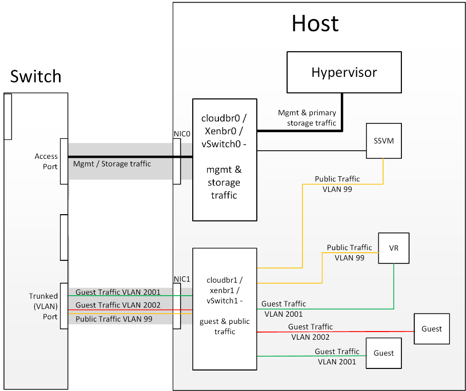
Figure 1: Hypervisor communications

Separating Primary Storage traffic For those from a pure virtualisation background, the concept of creating a specific interface for storage traffic will not be new; it has long been best practice for iSCSI traffic to have a dedicated switch fabric to avoid any latency or contention issues. Sometimes in the cloud(Stack) world we forget that we are simply orchestrating processes that the hypervisors already carry out and that many ‘normal’ hypervisor configurations still apply. The logical reasoning which explains how this splitting of traffic works is as follows:

  1. If you want an additional interface over which the hypervisor can communicate (excluding teamed or bonded interfaces) you need to give it an IP address.
  2. The mechanism to create an additional interface that the hypervisor can use is to create an additional management interface
  3. So that the hypervisor can differentiate between the management interfaces they have to be in different (non-overlapping) subnets
  4. In order for the ‘primary storage’ management interface to communicate with the primary storage, the interfaces on the primary storage arrays must be in the same CIDR as the ‘primary storage’ management interface.
  5. Therefore the primary storage must be in a different subnet to the management network

subnetted storage interfaces 
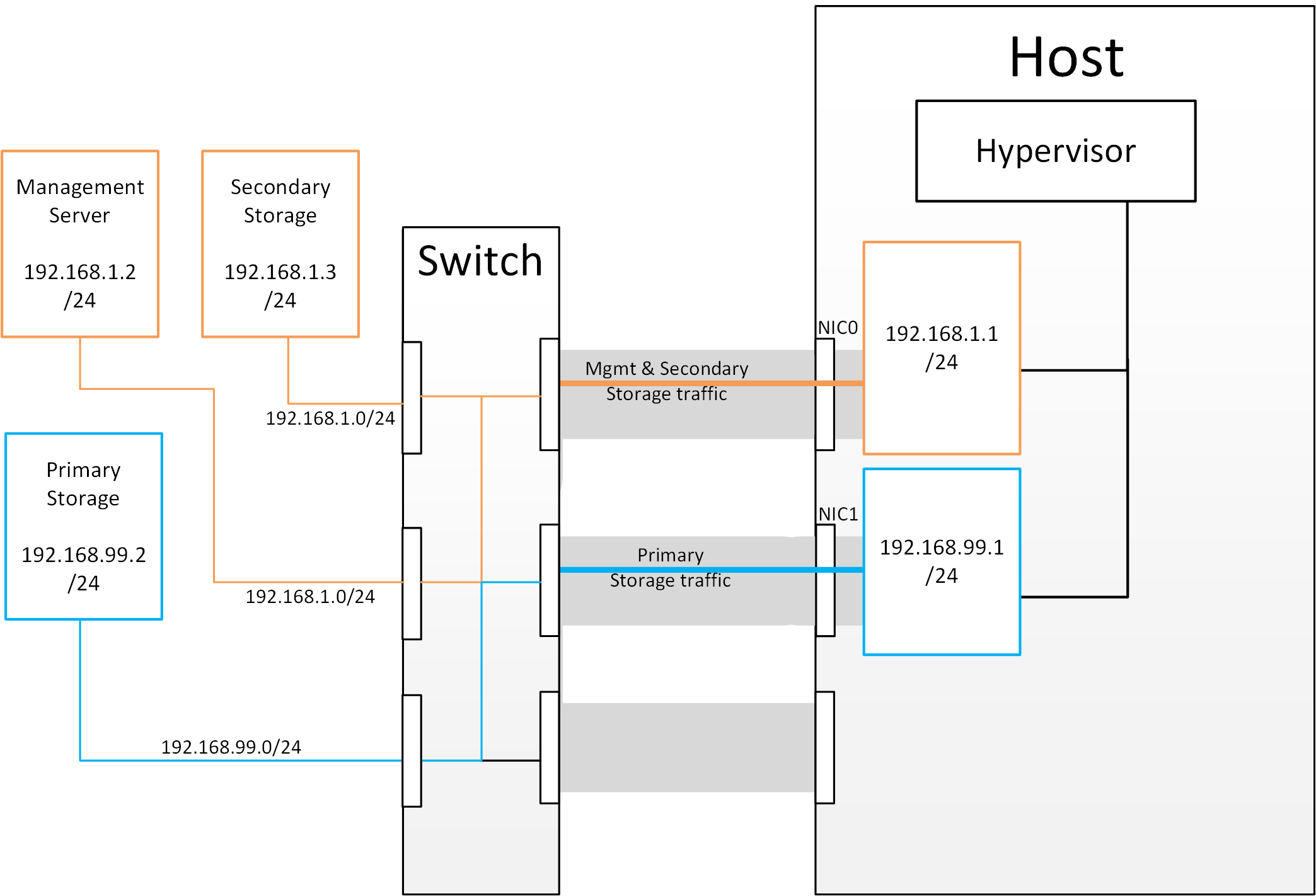
Figure 2: Subnetting of Storage Traffic

hypervisor communications to secondary storage 
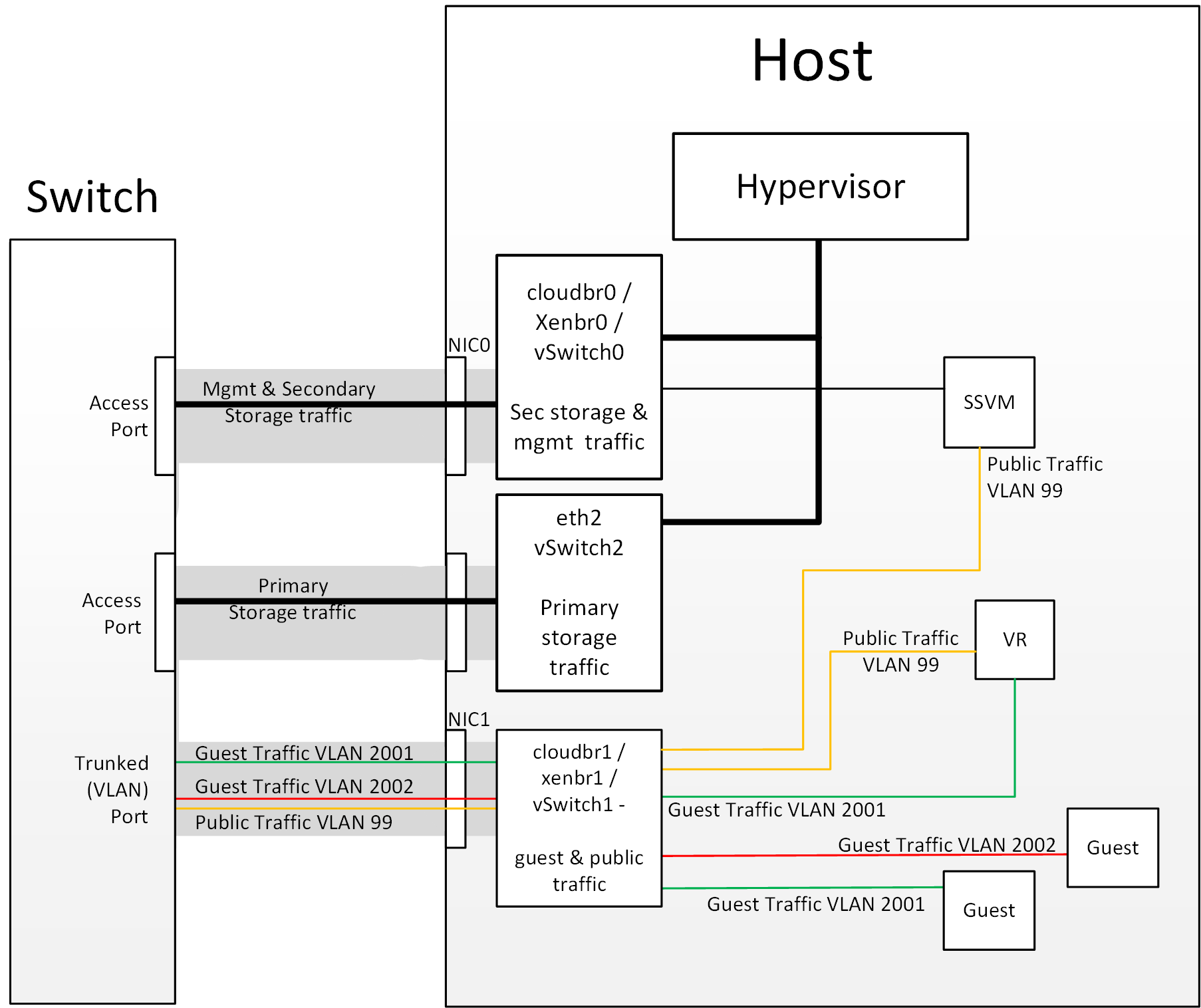
Figure 3: Hypervisor Communications with Separated Storage Traffic

Other Primary Storage Types If you are using PreSetup or SharedMountPoints to connect to IP based storage then the same principles apply; if the primary storage and ‘primary storage interface’ are in a different subnet to the ‘management subnet’ then the hypervisor will use the ‘primary storage interface’ to communicate with the primary storage.

Small-Scale Example Configurations

在本节中我们将通过几个实例说明,如何设置存储并使NFS和iSCSI存储系统正常工作。

基于本地硬盘和DAS的NFS服务

本节描述如何在一个标准的Linux系统中配置NFS输出。具体的命令取决于操作系统版本。

  1. 在存储服务器上安装RHEL/CentOS 发行版

  2. 如果根卷的大小超过2TB,创建一个小点的启动卷用于安装RHEL/CentOS,根分区保留20GB就足够了。

  3. 系统安装好以后,创建一个名为 /export的目录。可以在根分区下创建,或者挂载一个较大的磁盘卷。

  4. 如果你在一台主机上有超过16TB的存储空间, 则创建多个EXT3文件系统和多个NFS输出,单个EXT3文件系统不能超过16TB。

  5. /export目录创建后,运行如下命令配置NFS输出。

    # echo "/export <CIDR>(rw,async,no_root_squash,no_subtree_check)" >> /etc/exports
    

    根据你的部署需求,调整如上参数。

  • 限制NFS输出. 强烈建议通过指定子网掩码来限制NFS访问权限,(例如“192.168.1.0/24”)。只允许规定的集群才能访问, 避免非集群成员访问。 且管理网络和存储网络必须能够访问;如果2个网络相同,那么一个CIDR就足够了。 如果你是单独的存储网络那么必须提供独立的CIDR或者一个足够大的CIDR可以包含它们2个。

下面是一个分隔的CIDRs的示例:

/export 192.168.1.0/24(rw,async,no_root_squash,no_subtree_check) 10.50.1.0/24(rw,async,no_root_squash,no_subtree_check)
  • 移除async异步标记. 标志允许NFS服务器在提交并写入磁盘操作前就先返回相应,来提高性能。请在关键生产部署中移除异步标志。
  1. 运行下面的命令启动NFS服务。

    # chkconfig nfs on
    
  2. 编辑/etc/sysconfig/nfs,并取消如下行的注释。

    LOCKD_TCPPORT=32803
    LOCKD_UDPPORT=32769
    MOUNTD_PORT=892
    RQUOTAD_PORT=875
    STATD_PORT=662
    STATD_OUTGOING_PORT=2020
    
  3. 编辑/etc/sysconfig/iptables,添加如下行的记录到INPUT链的开始部分。

    -A INPUT -m state --state NEW -p udp --dport 111 -j ACCEPT
    -A INPUT -m state --state NEW -p tcp --dport 111 -j ACCEPT
    -A INPUT -m state --state NEW -p tcp --dport 2049 -j ACCEPT
    -A INPUT -m state --state NEW -p tcp --dport 32803 -j ACCEPT
    -A INPUT -m state --state NEW -p udp --dport 32769 -j ACCEPT
    -A INPUT -m state --state NEW -p tcp --dport 892 -j ACCEPT
    -A INPUT -m state --state NEW -p udp --dport 892 -j ACCEPT
    -A INPUT -m state --state NEW -p tcp --dport 875 -j ACCEPT
    -A INPUT -m state --state NEW -p udp --dport 875 -j ACCEPT
    -A INPUT -m state --state NEW -p tcp --dport 662 -j ACCEPT
    -A INPUT -m state --state NEW -p udp --dport 662 -j ACCEPT
    
  4. 重启服务

    NFS共享目录/export已经被创建

注解

当复制和粘贴命令时,请确保没有多余的换行符,因为一些文档查看器可能会在复制时加上换行符。

基于iSCSI的NFS服务

使用以下步骤创建基于iSCSI卷的NFS服务。这些步骤适用于RHEL/CentOS 5发行版。

  1. 安装iscsiadm。

    # yum install iscsi-initiator-utils
    # service iscsi start
    # chkconfig --add iscsi
    # chkconfig iscsi on
    
  2. 发现ISCSI target。

    # iscsiadm -m discovery -t st -p <iSCSI Server IP address>:3260
    

    例如:

    # iscsiadm -m discovery -t st -p 172.23.10.240:3260 172.23.10.240:3260,1 iqn.2001-05.com.equallogic:0-8a0906-83bcb3401-16e0002fd0a46f3d-rhel5-test
    
  3. 登录

    # iscsiadm -m node -T <Complete Target Name> -l -p <Group IP>:3260
    

    例如:

    # iscsiadm -m node -l -T iqn.2001-05.com.equallogic:83bcb3401-16e0002fd0a46f3d-rhel5-test -p 172.23.10.240:3260
    
  4. 发现SCSI磁盘,例如:

    # iscsiadm -m session -P3 | grep Attached
    Attached scsi disk sdb State: running
    
  5. 格式化磁盘为ext3类型并挂载卷。

    # mkfs.ext3 /dev/sdb
    # mkdir -p /export
    # mount /dev/sdb /export
    
  6. 添加磁盘到/etc/fstab并确保在启动时能被挂载。

    /dev/sdb /export ext3 _netdev 0 0
    

现在你可以建立/export共享目录

  • 限制NFS输出. 强烈建议通过特定的子网和掩码限制NFS访问权限(例如”192.168.1.0/24”), 只允许规定的集群才能访问, 避免非集群成员访问并非故意的情况下删除所有数据。 且管理网络和存储网络必须能够访问;如果2个网络相同,那么一个CIDR就足够了。 如果你是单独的存储网络那么必须提供独立的CIDR或者一个足够大的CIDR可以包含它们2个。

    下面是一个分隔的CIDRs的示例:

    /export 192.168.1.0/24(rw,async,no_root_squash,no_subtree_check) 10.50.1.0/24(rw,async,no_root_squash,no_subtree_check)
    
  • 移除async异步标记. 标志允许NFS服务器在提交并写入磁盘操作前就先返回相应,来提高性能。请在关键生产部署中移除异步标志。